KERMIT: CV Line-Following Bot
Preface
I never expected a simple line-following robot to become the source of so much frustration and relentless debugging, especially for a task that’s often the go-to project in middle school robotics clubs. The challenge, however, lay in one key constraint: we couldn’t use the typical pair of IR sensors. Instead, we had to rely on a camera.
Design
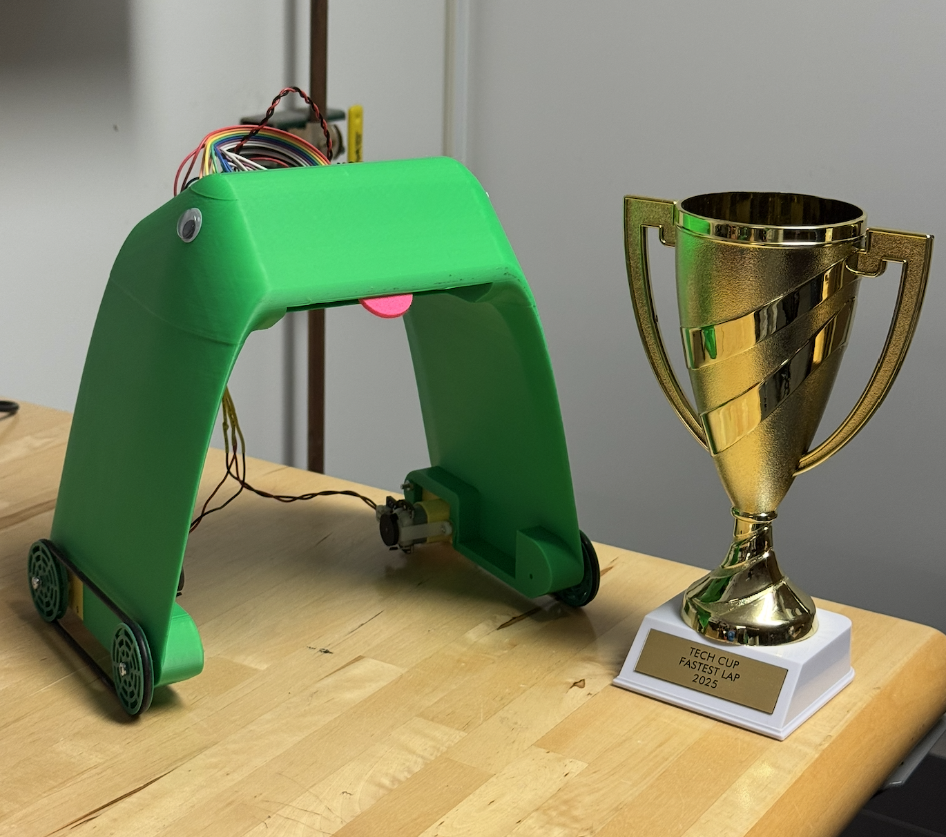
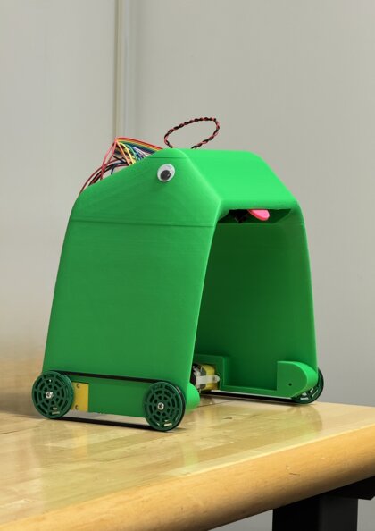
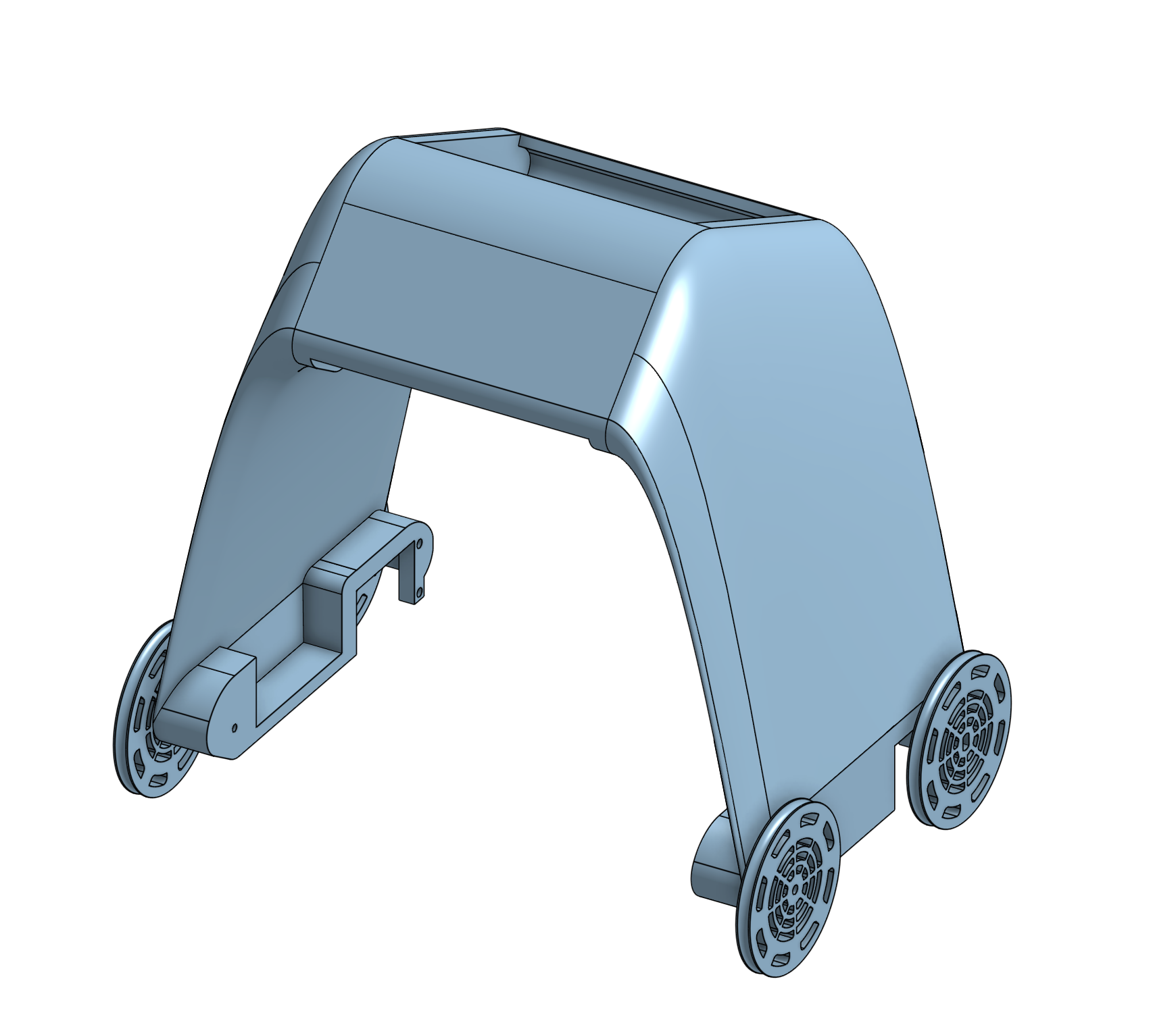
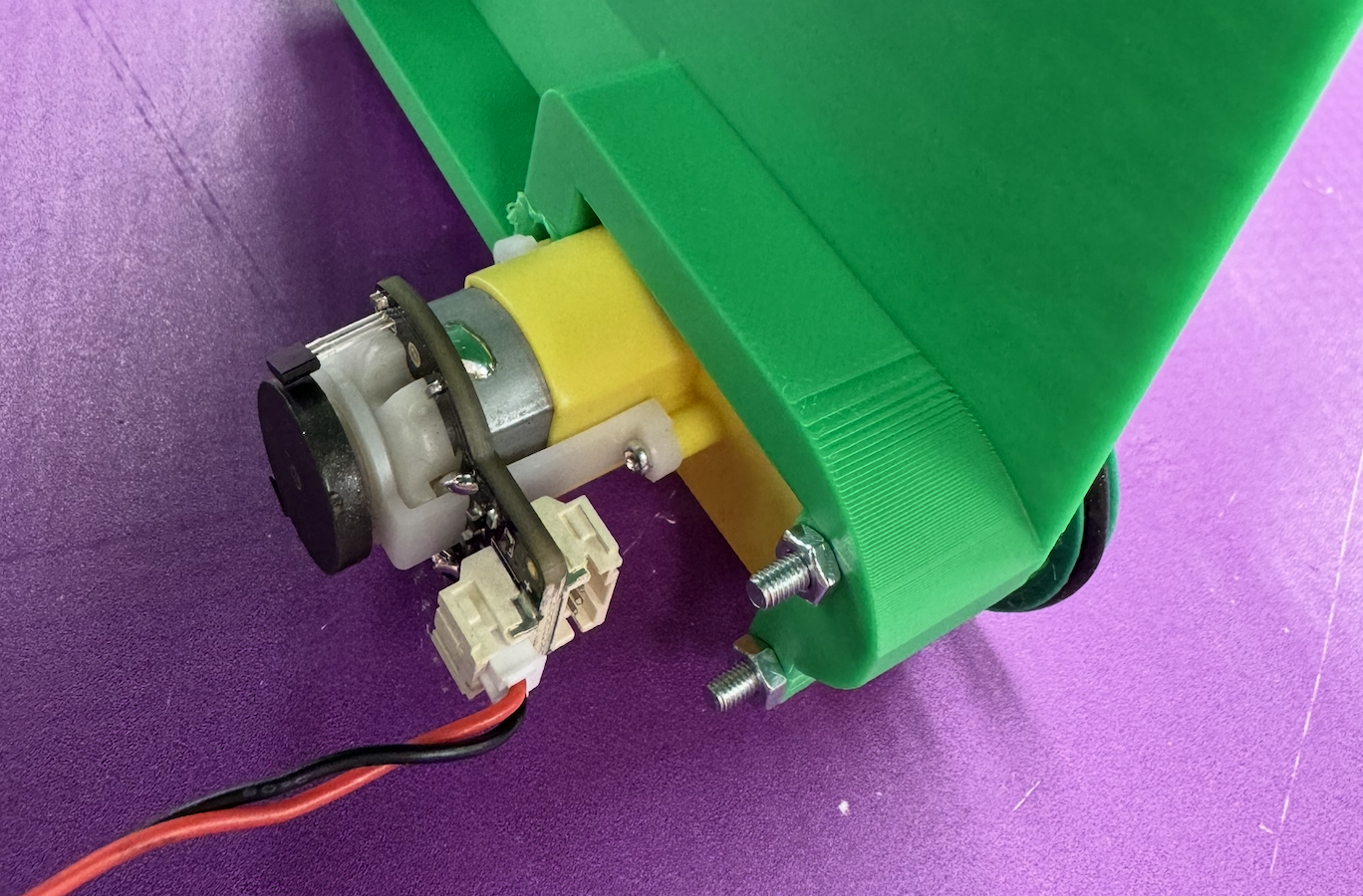
KERMIT is a frog. He identifies as one, and as such, his body is designed to be as frog-like as possible. He has a flat head, googley eyes, and two long powerful legs. His toungue is not as impressive as some of the other frogs out there, which leads some to think that he’s actually a toad. But KERMIT is a frog, and he’s proud of it.
Electronics
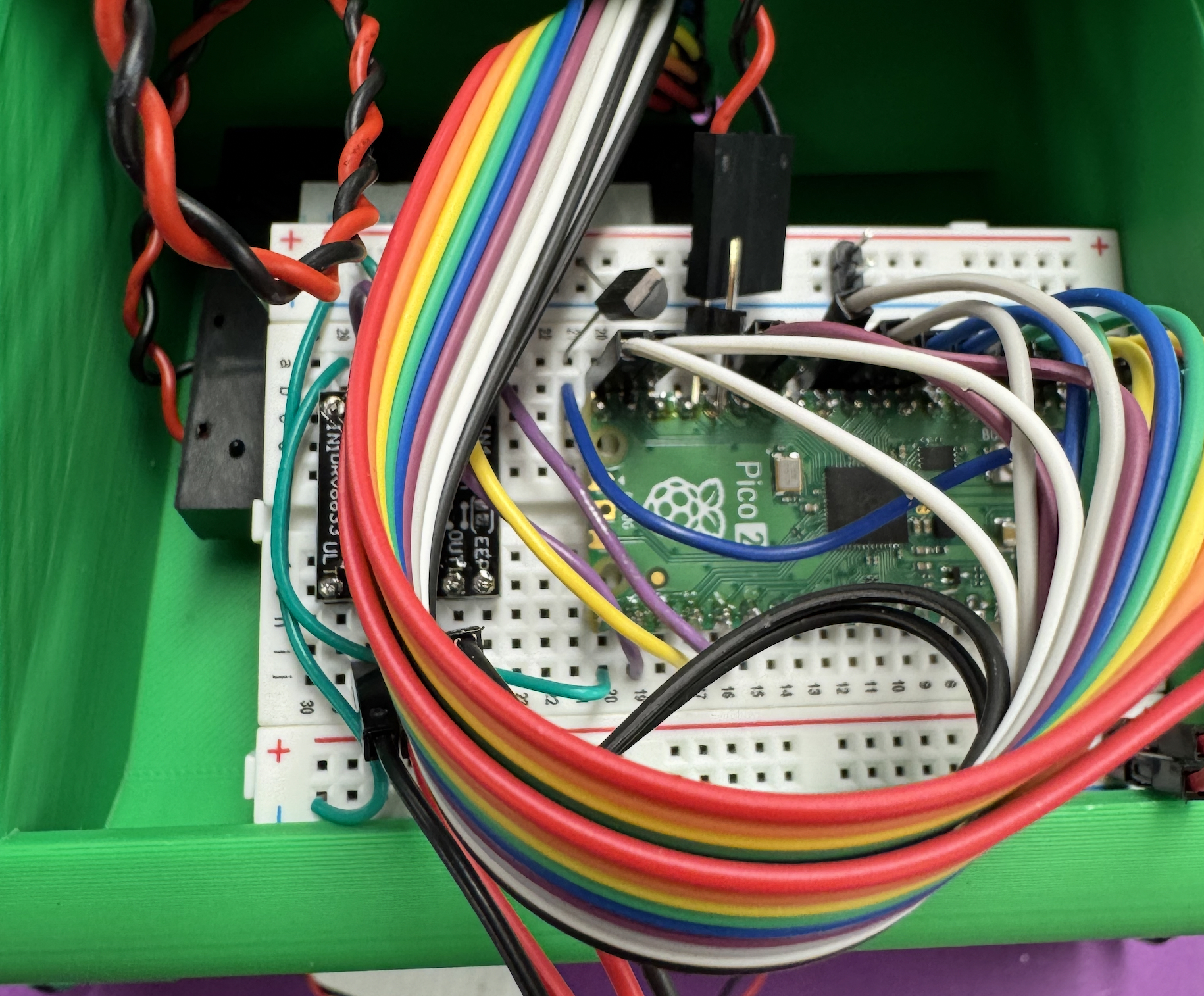
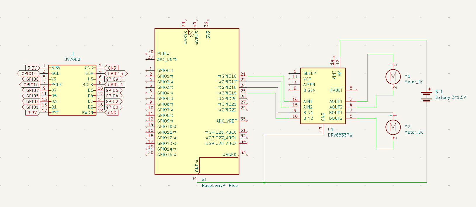
The electronics for KERMIT are rather simple. A Raspberry pi pico is connected to a OV7670 camera module and a DRV8833 H-bridge motor driver to drive the two motors. The circuit is mounted on a breadboard and is powered by 3 AA batteries.
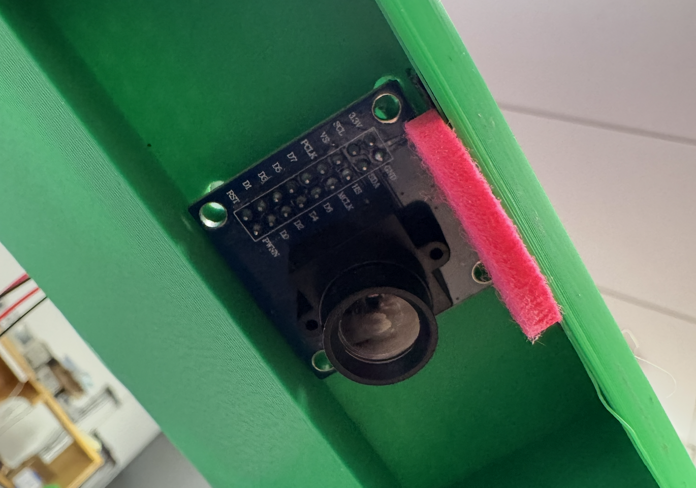
Camera
KERMIT uses his camera to calculate the position of the center of the line by finding the “center of brightness” in the image. The line he’s supposed to follow is a thick white line on a dark purple backdrop, so this system works pretty well. The function which finds this value is provided by our corse instructor Prof. Marchuk.
Since the line will (ideally) be perpendicular to the camera, we find the average brghtness of a row.
int sumBright = 0;
    for(i=0;i<IMAGESIZEX;i++){
        sumBright = sumBright + picture.r[r+i] + picture.g[r+i] + picture.b[r+i];
    }
    int avgBright = sumBright / IMAGESIZEX;
Next, we threshold the row, setting all pixels below the average brightness to black and all pixels above to white.
    for(i=0;i<IMAGESIZEX;i++){
        int mass = picture.r[r+i] + picture.g[r+i] + picture.b[r+i];
        if (mass < avgBright){
            // not bright enough, set pixel to black
            picture.r[r+i] = 0;
            picture.g[r+i] = 0;
            picture.b[r+i] = 0;
        }
        else {
            // set to white
            picture.r[r+i] = 255;
            picture.g[r+i] = 255;
            picture.b[r+i] = 255;
        }
    }
Lastly, we return the calculated center of mass, which results in a value ranging from 0 to IMAGESIZEX, whcih is 60 pixels.
for(i=0;i<IMAGESIZEX;i++){
        int mass = picture.r[r+i] + picture.g[r+i] + picture.b[r+i];
        sumMass = sumMass + mass;
        sumMassR = sumMassR + mass*i;
    }
    float centerOfMass = (float)sumMassR / sumMass;
    return (int)(centerOfMass);
Motor Control
The value from the camera is then used in the main program to control the robot’s motors through a simple PID controller. The value is mapped to a float that ranges from -1 to 1, where -1 is full left and 1 is full right.
if (com >= line_center) {
            // Left side mapping (values higher than line_center are to the left)
            if (com >= spread_left) {
                control = -0.5f * pid_range; // Clamp to maximum left turn
            } else {
                // Map from line_center to spread_left
                control = -0.5f * pid_range * ((float)(com - line_center) / (float)(spread_left - line_center));
            }
        } else {
            // Right side mapping (values lower than line_center are to the right)
            if (com <= spread_right) {
                control = 0.5f * pid_range; // Clamp to maximum right turn
            } else {
                // Map from line_center to spread_right
                control = 0.5f * pid_range * (1.0f - ((float)(com - spread_right) / (float)(line_center - spread_right)));
            }
        }
This value is then used to drive the robot using a driver function.
void drive_robot(float control) {
    // Clamp control value between -1 and 1
    if (control < -1.0f) control = -1.0f;
    if (control > 1.0f) control = 1.0f;

    float left_speed = 1.0f;  // Left wheel speed (0.0 to 1.0)
    float right_speed = 1.0f; // Right wheel speed (0.0 to 1.0)

    // Adjust wheel speeds based on control value
    if (control > 0) {
        // Turning right (reduce right wheel speed)
        right_speed = 1.0f - control;
    } else if (control < 0) {
        // Turning left (reduce left wheel speed)
        left_speed = 1.0f + control; // Note: control is negative here
    }

    // Set motor speeds for forward motion
    set_motor_speed(M1F, left_speed);  // Left forward
    set_motor_speed(M1B, 0);           // Left backward off
    set_motor_speed(M2F, right_speed); // Right forward
    set_motor_speed(M2B, 0);           // Right backward off
}
Conclusion
KERMIT was a fun project to work on, and by extension, MECH_ENG 433 as a course. I’ve never used a Raspberry pi pico, and after taking this class, I think I will be using it a lot more for my personal projects in the future. The pico is certainly a powerfull MCU at such a competitive pricepoint and I’m excited to see what I can build with it.
The course was super chill, and I never felt like I was being pushed to do anything, but rather encouraged to explore and experiment. I would recommend any engineering student at NU to take a jab at the course, as it’s a great way to learn about mechatronics and embedded systems.